Digital Multimeter
A multimeter is a most essential tool for testing or checking various electronics components, when it comes to creating or developing electrical circuits. Without it, executing a job will be extremely tough.
So, in this post, we chose to create a low-cost digital multimeter using Arduino and other basic components. When it comes to the multimeter’s functions, it can measure voltage up to 24V, as
well as diode, resistance, and voltage drop across an LED.
- It also includes a continuity feature with a buzzer, so you can use it to identify short circuits.
- We can have build many projects in the field of measuring instruments like,
- IoT Based Electricity Energy Meter using ESP12 and Arduino
- Measuring water Flow Rate and Volume using Arduino and Flow Sensor.
- DIY GPS Speedometer using Arduino and OLED Speed, Distance and Angle Measurement for Mobile Robots.
- You can check the above projects if you are interested in the topics.
Components Required to Build Digital Meter:
- Arduino Pro Micro – 1
- Push Button – 1
- 1K Resistor – 1
- 10K Resistor – 1
- 4.7K Resistor – 2
- Active Buzzer – 1
- 0.91” 128×32 OLED – 1
- Toggle Switch – 1
- Banana Socket – 4
- 3.7V, 300mA lithium
- Battery – 2
- AMS1117-5.0 – 1
- Perf Board – 1
- Connecting Wires – 1Circuit Diagram of Arduino Digital Multimeter
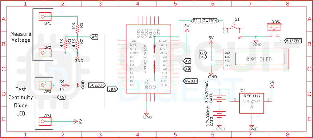
The complete schematic diagram of the Arduino Digital Multimeter is shown below. The schematic is simple and easy to understand
The working of the schematic is simple: we have Arduino working as the brains of our project. In the circuit we have used two pairs of banana connectors for connecting external
input. As you can see in the above diagram, we have a 10K resistor and two 4.7K resistors in parallel to form a voltage divider. With this voltage divider configuration and
Arduino, we can measure input voltage max 24V. Please note that input voltage more than 24V can damage the device. Next, we have another pair of banana sockets that are for
testing continuity Diode and LED, these tests are done by measuring a certain voltage drop across the test device. We also have connected a 0.91” OLED display to display all the
data processed by the Arduino and we have a push button switch for toggle between all features of this multimeter. Finally, we have two 3.7V battery packs in series and an
AMS1117-5.0 5V regulator to power the total circuit.
We previously used Arduino to build many test and measure instruments:
Frequency Counter using Arduino
Arduino Ohm Meter
Capacitance Meter using Arduino
LC Meter using Arduino: Measuring Inductance and Frequency
Measure Sound/Noise Level in dB with Microphone and Arduino
